CanalNetworkDocs
Design of Division Boxes
CanalNETWORK software can handle the design and estimation of canal junction structures. By default, every canal junction is designed as a turnout structure. If any junction is required to be designed as, and function as, a division box structures, the user must indicate this by checking the Div. Box check box on the Node Edit panel.
![[ ]](Images/Image%20001.png)
Division Box check box in Node Edit Panel.
Note: A confirmation is required to proceed. The message box informs the user of eminent changes to the data of the node in question.
This guide describes the method and procedure used in the design and documentation of division box structures in CanalNETWORK product.
Design Approach to Division box
The design approach implemented in CanalNETWORK product is taken from a guideline from ECDSWCo. (See Reference at the end). The division box design method adopting broadcrested weir as flow divisor is implemented in CanalNETWOEK product.
The governing flow equation is:
Q= 1.7 B H^(1.5)
Where:
-
Q is the discharge flowing over the crest
-
H is the head of flow overt the crest
-
B is the overflow length, or the width of the Notch.
The soution to this equaiton is determined based on the Modular Limit criteria. This means that, the flow over the weir is independent of variations in tail water level. For this to occur, the tail water energy level must not rise above a certain percentage of the upstream energy head over the weir crest. A limiting value of z= 1/3H is used.
The steps implemented are summarized as below:
-
Detemine the available overflow head, H, from either upstream flow depth y, or 0.5Thk (Thk=0.40 is used). This will ensure that the assumed broad crested weir flow condition occurs.
This will fix the overflow crest level to each branch canal.
-
Compute the required overflow length from
w= Q/1.71/H^1.5
Then determine individual lengths of overflow notch for each branch canal from the proportional flow equation:
wi= w*qi/Q
-
From a known headloss amount of z (above), determine the pre-jump and post-jump depths for the flow condition after the crest and in to the downstream basin of each branch canal. Blenchs curve method is used. This is used to determine:
Lbasin= 5*(Y2-y1), length of the stilling basin required behind the crest
hSill= y-y2, but not less than 0, height of stilling pool end sill
-
Finally the CBL levels for each branch canal are fixed based on z, hSill and FSL values.
The algorithm will not accept parent canal capacities exceeding 80litres per second, or the throws the following error message:
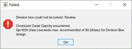
Error message for parent canal capcity Q=0.939m3/sec
There are certain conditions that a node must fulfil to be hydraulically solved. Incoming and outgoing discharges must be comparable. Specifically
-
No branch canal can have larger capacity than the incoming (parent) canal
-
The sum of outgoing discharges can not be above 5lpsec beyond the parent canal capacity
-
Difference between parent canal discharge and sum of all outgoing discharges can not be more than 20% of the parent canal capacity.
Conditions not meeting the above criteria are likely impractical, and hence not solved. In such cases:
a. An error message, such as below, is reported
b. The check mark assignment is reversed, and the junction is retained as a turnout structure.
![[ ]](Images/Image%20007.png)
Error message for unbalaned discharge condition.
Upon succesful solution to the above iterative process, the algorith assigns dimensions to the corresponding branching canal as follows:
-
Overflow Width, B= max (0.3, H1, Lc/5), where Lc= 2*H1
-
Crest Height, ds= Crest Level - Parent Invert
-
CBL branch= CBL parent + Y - z - y, where Y and y are the flow depths in the parent and branch canals respectively.
-
L branch= 5*(H1-H2)
The actual dimension tables and designed invert levels for the parent and branch canals can be found from Explore Solutions > Data Tables > Explore Division Boxes. A table similar to below content is displayed.
![[ ]](Images/Image%20005.png)
![[dsfs]](Images/Image%20006.png)
Typical table report generated for the design of a division box.
Where:
-
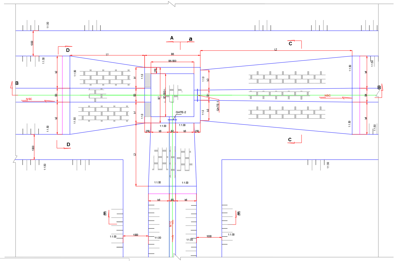
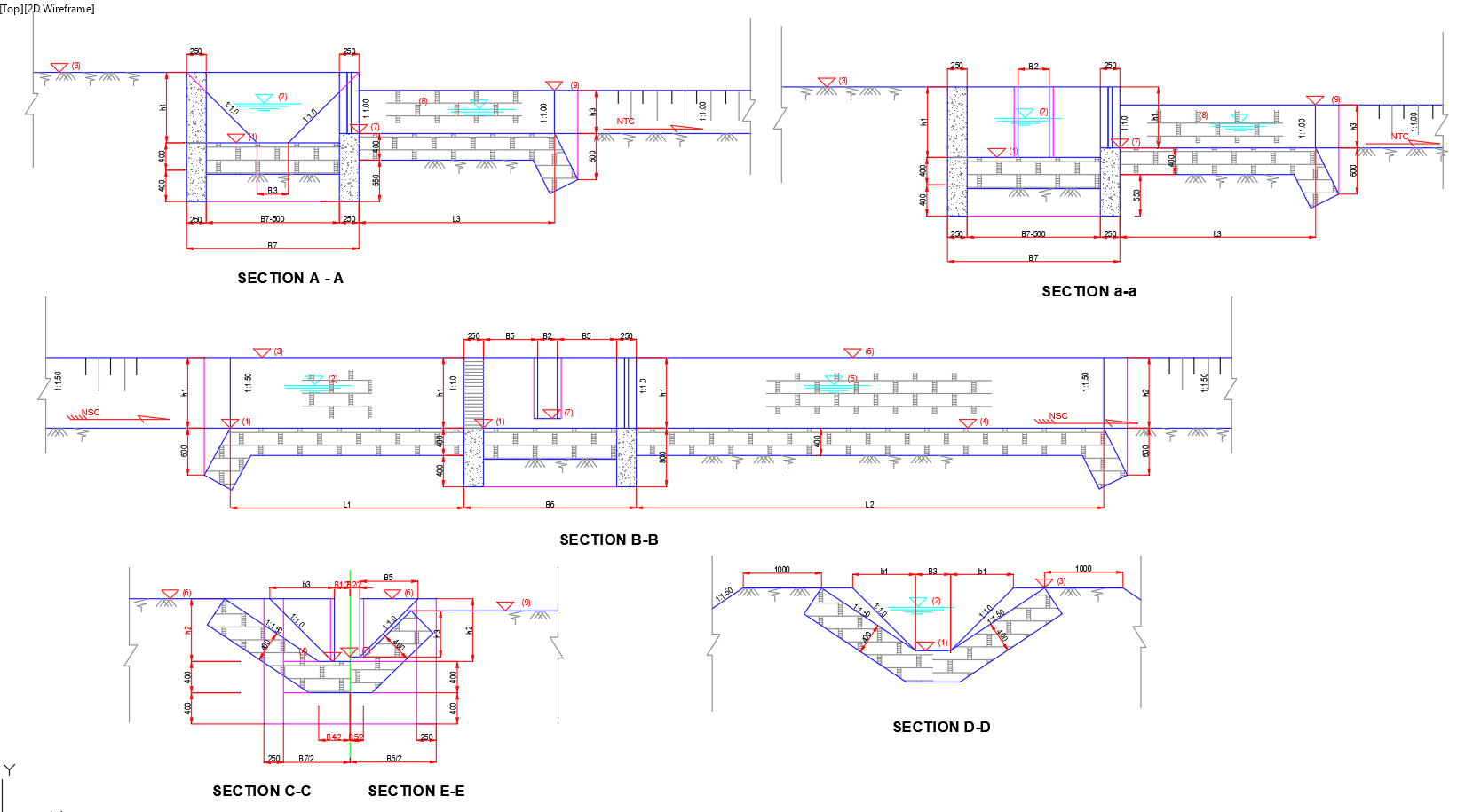
all symbols in the dimension table are defined in the below drawings
-
W1, H1 are the notch opening dimensions to the branch canal
-
W2, H2 are the notch opening dimensions to the continuing canal
Note: The above results are for a two way divison box, where a parent canal feeds water to a branch canal, and a continuing canal. Where merged nodes exist, the division box is a three way structure. In such cases, an other line of results is generated indicating dimensions for outlet to the remaining branch canal.
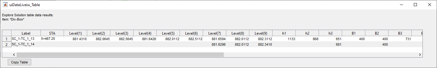
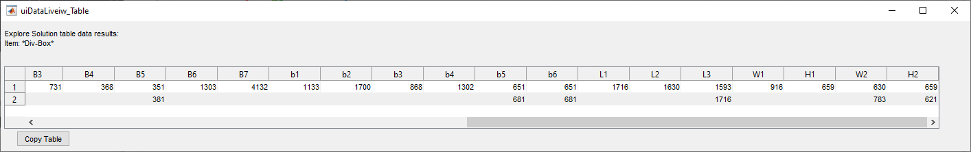
Figure showing two line output of report table, for a three way division box. Note, only dimensions pertinent to the third outlet are indicated in the second line. Notice also the label for each row of result.
Generating Design Report
The results of the above algorithm for a certain division box can be generated from the R (Redesign) button located right next to the Div. Box check mark in the Node Edit panel area.
Click on this button, a report of similar to the one shown below is generated.
![[ ]](Images/Image%20003.png)
Report generator setting dialog.
![[ ]](Images/Image%20004.png)
Sample report for a division box design
BoQ generation
BoQ is estimated using the dimensions generated in the preceeding table, and the standard drawings below.
A sample BoQ for a division box looks similar to below output.
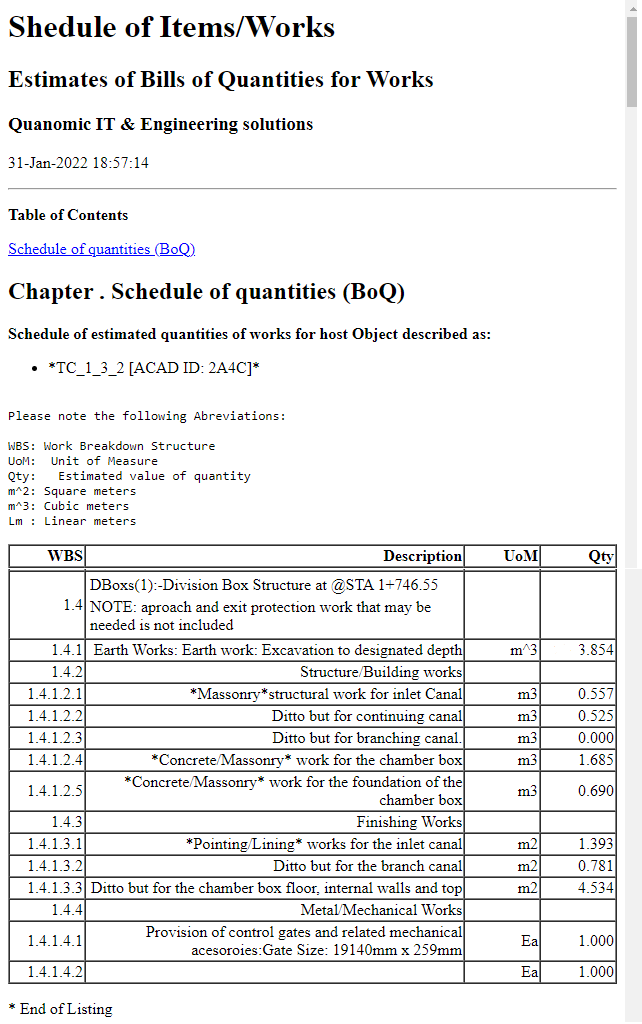
Sample output of BoQ listing for a division box.
END.
Regerences: A guideline for Design of Division Box Structures, Feb 2015, IDFP Design Team, Water Works Design and SUpervision Enterprise, Addis Ababa.