CanalNetworkDocs
Farm Blocks and Network Sizing
One of the key strengths of CanalNETWORK software is high level of task automation avaiable for time consuming and error prone tasks. Once a network of canals is succesully imported and resolved, subsequent tasks are easy to manage, giving users a quick turnarround time for their projects. Farmblock analysis functionality is one of such many features.
Farmblock tools assist to identify and calculate irrigation areas for the lowest level(s) of canals in a given netowrk, and cummulate the values towards the primary level canals. This process facilitates two important stages of the design:
-
Accurately determine the net irrigable area of the network, or its sub-networks, or any other level of canal.
-
Size each segment of canal in the entire network with our requiring further input from the user (using duty assigned in the design criteria).
Sizing of canal segments, refers to the determination of amount of discharge passing through each segment of each route of the network canals.
These, otherwise time consuming tasks can be completed in a matter of a few seconds in CanalNETWORK software, with quality and speed.
Farm Blocks
First, let’s see ways to create farm block information. There are two methods:
-
Read drawing objects representing farm blocks in AutoCAD. This is the most accurate method, and also can be very time consuming.
-
Automatically estimate the area each canal may be serving. This is a quick process, and also the least accurate. Note that this is only an esimtate.
The two methods are described below.
Farmblocks from AutoCAD
To read farmblock area data from AutoCAD, first create the farm blocks using polyines. There are a few ways to draw farm blocks.
-
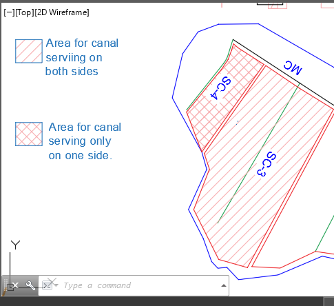
Field canal irrigating to both sides: Draw ensclosing polyline objects around the area served by the field canal.
-
Field canal irrigating only either to the left or to the right: creat a polygon area covering the area served by the canal, and add a zero area extension at a location convenient to cross with the feeded canal.
To add a zero area extenaion, click on the boundary and hover over the vertex you want to edit and choose
Add Vertexmenu item.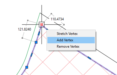
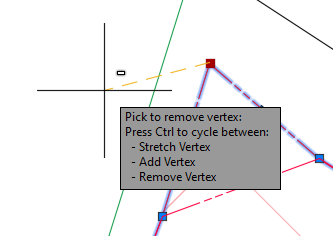
Pick a location over the other side of the canal.
Finally modify the resulting geometry by moving the next vertes to over lap with the previous vertex.
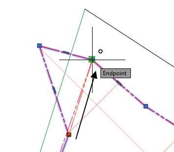
The final geometry is shown above. This ensures the the area crosses the desired canal route, with out any change on the area of the block area delineated (hence the term zero-area extension.)
Note: Each farmblock area should cross ONLY one serving canal. The converse is also true, i.e., each canal should only be crossed by one farmblock boundary. Otherwsie, the first canal that is found to cross with a given farmblock is assigned the area of the farmblock.
Once these are ready:
-
Collect all farm blocks to fascilitate easy import. This can be done in either of two ways. Either instantiate all the farm blocks in to one or few host objects, or construct/ move all farm block boundaries to a separate layer.
-
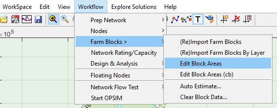
To import from a host instance object go to
Workflow > Farm Blocks > (Re)Import Farm Blocks...menu command. To import from layer go toWorkflow > Farm Blocks> (Re)Import Farm Blocks By Layer...Both methods are valid.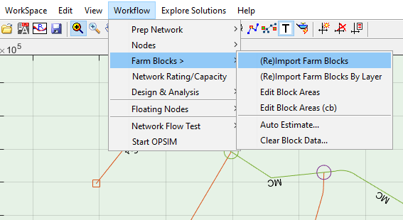
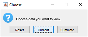
This will start the Choose dialog.
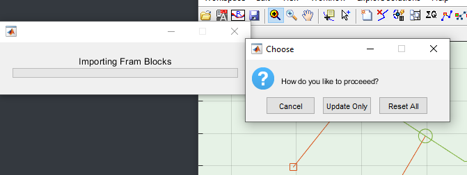
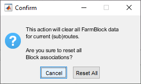
If importing for the first time, or desire to overwrite all existing associated data, choose
Reset All. If you want to append the current collection to the existing data, chooseUpdate Only. For the case under consideration, Reset All would be the right choice, so hit the corresponding button.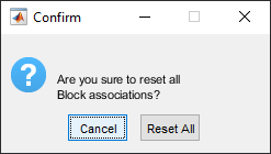
Confirm the action in the dialog.

The Done dialog completes import process. The farmblocks imported are shown in the layout view area overlapping the network elements.
At this stage you can view the quantities of areas associated to each serving canal route, by using View > Route Text > Select & Show Text... and picking A field in the dialog.
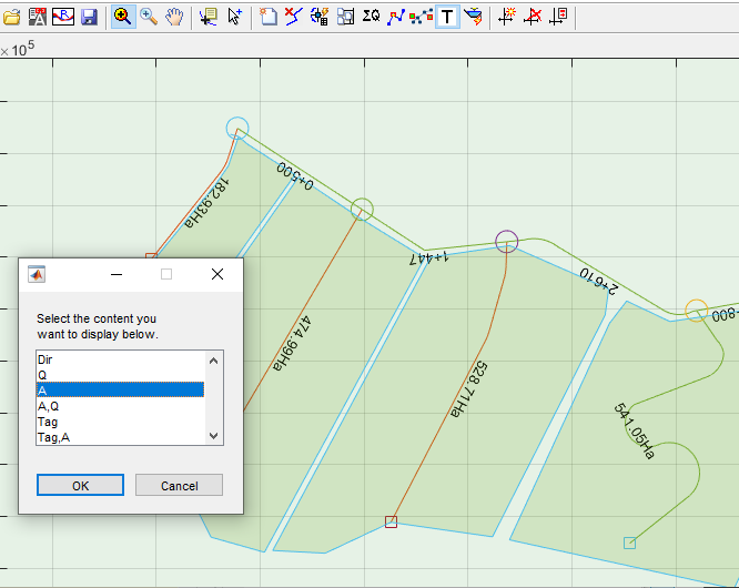
You can also generate a table from View > Workflow > Farm Blocks > Edit Blocks... , and selecting Current when prompted.
One can modify the block data for any one route at any time, in one of two ways:
(a) by simply ReImporting the farm block object corresponding to the route. In this case you should choose Update Only button when prompted.
(b) by starting the Edit Block menu command, choosing Reset and editing the areas manually. Some times, geometrically editing farm blocks may not be a choice for the engieer. Rather editing a table may be required. This may be the case for canals in existing projects whose area is already prescribed. In this case:
-
Start Edit Blocks menu command as above
-
Choose
Reset. This will erase any cummulative area information in the network and reset data to the original data during import. -
simply start editing in the table, and hit
Apply.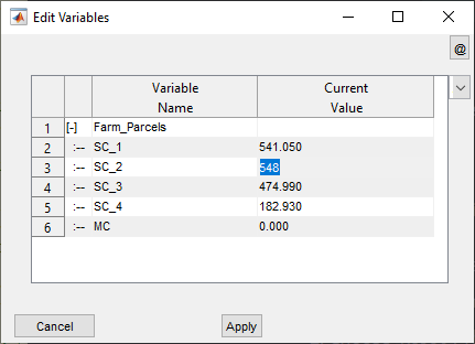
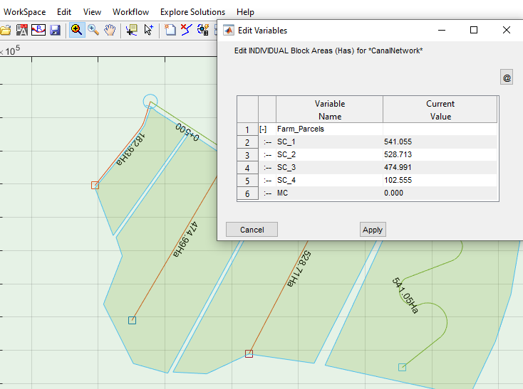
You can see that, the area corresponding to the parent canal is 0.00. This is because it does not serve a particular farm block. The area it serves shall be determined from cummlative of the areas that the sub-canals serve individually. To do this,
-
First select the primary most canal for the network, to indicate the final direction of cummulation.
-
Then go to
Workflow > Farm Blocks > Edit Block Areas...and chooseCummulatebutton. -
The table data is updated to show the cummulated area each route is serving, as shown below. Hit
Applyto continue to the next step.
Note: Area served is shown as a label in the layout view area ONLY for canals associated with Farm Blocks. Other canal routes will show Canal capacities as available.
Note: If farm block data is updated, DO NOT forget to cummulate areas again to reflect the changes in the table, and
Applythe new figures to the data base.
Automatically created farm parcels
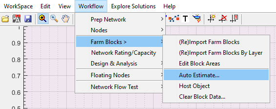
Where fast estimates are required, the auto estimator tool can be used. The tool is available from Workflow > Farm Blocks > Auto Estimate... as shown below.
Note: This should be applied on a fully resolved network, else errors will be encountered in the process.
To use the tool:
-
Start it as described above.
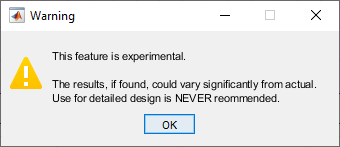
Upon initiating the warning dialog appears, reiterating the results - if any is found - are approximate.
Accept the subsequent confirm action messages.
-
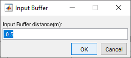
Next, you are prompted to provide a bugger distance. This value is used to determine the distance beween adjacent farm blocks. Note the value is a negative value, indicating that the areas determined will be shrinked away from boundary lines determined by the algorithm.
-
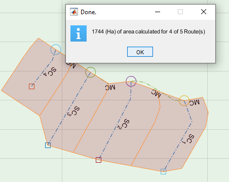
The final result is presented as shown below, giving the sum total of farm parcel areas found for the network. You can see that the blocks are only calculated for the last generation canals.
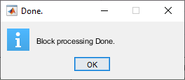
The process ends with the below dialog.
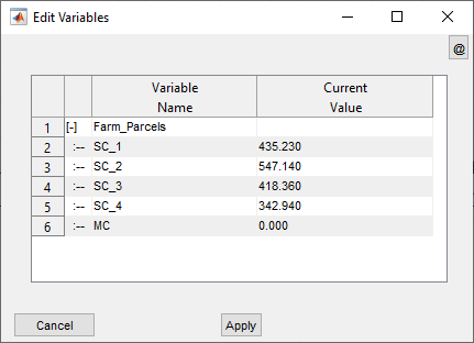
The above process, has already assigned each route in the network with the corresponding estimated areas of the farm parcel area. This can be viewed from Workflow > Farm Blocks > Edit Block Area command. The procedure is same as that for the manual process described further above.
The table will display a result similar to below snapshot.
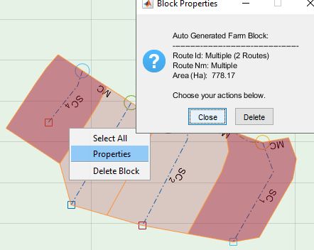
You can select/deselect parcels by left-clicking on them, and choose to delete them.
Note: Delete job can not be undone. You will have to regenerate the blocks again.
You can also view the size of selected parcels by rightclicking on them and choosing Properties.
Editing Automatically created farm blocks
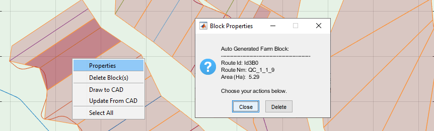
Farm blocks automatically created can be edited and updated by using the context menu accessed by right-clicking on any block.
To select blocks for processing, click on the desired blocks. The blocks will be selected or deselected accordingly. Use Select All option to select all blocks.
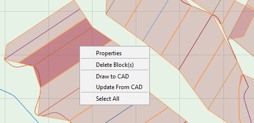
To view area and associated property, use the Properties context menu.
To Delete blocks, use Delete Block(s) context menu. This is helpful, when canals that do not supply water to fields are assigned a block.
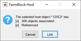
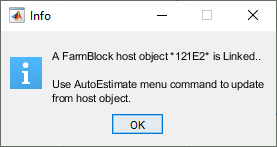
You can also draw the farm blocks to AutoCAD. This allows to easily edit the vertices of each farm block and update from it. To achieve this a farm block host object is required. The object must be referenced to the comman area reference axis, and tagged appropriately.
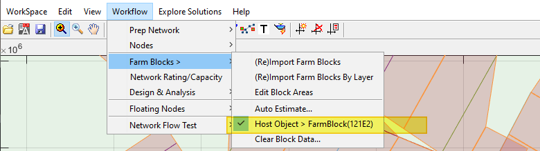
To Link a Host Object: go to WorkFlow > Farm Blocks > Host Object .
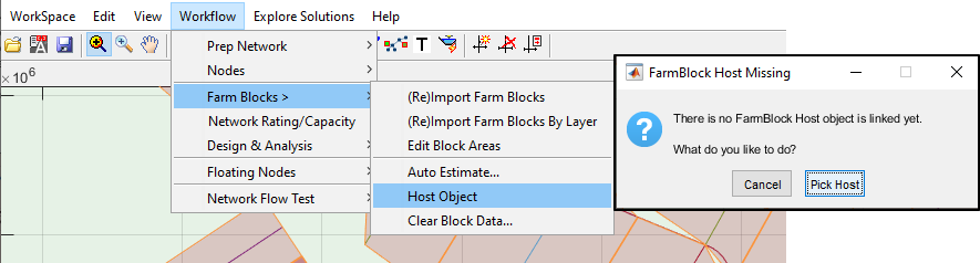
This will display the dialog showig the contents of the selected host object if any are found. Click on the Link button to accept.
Note: The menu item now shows the changes made.
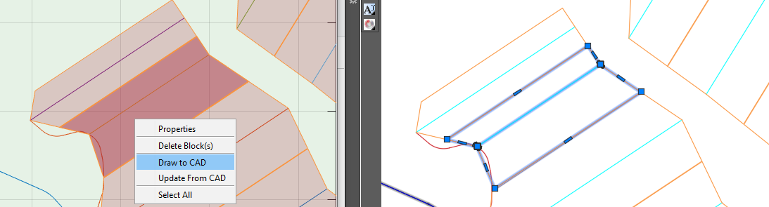
To draw blocks to AutoCAD, select the desired blocks and choose the Draw to CAD context menu. This will create the drawings to AutoCAD. You can edit the vetrices of any of the blocks.
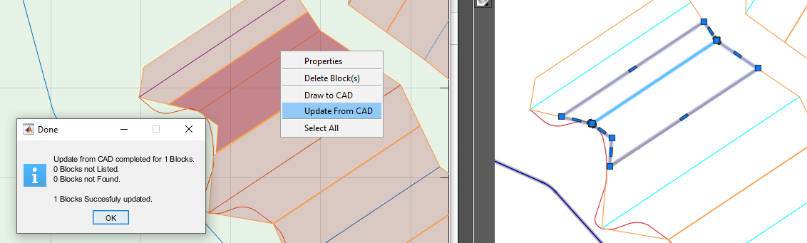
To update from the drawings, select the desired blocks to update, and choose Update from CAD context menu. A dialog will show
Such work saved in AutoCAD can be reloaded to the CanalNETWORK environment using Workflow>FarmBlocks> AutoEstimate... tool, if the FarmBlock Host object is available and linked.
Tips:
-
It is highly recommended to create and use a separate layer to contain the host object and the blocks of farm parcels. With the number of objects increasing in the AutoCAD environment, it may be hard to keep track of changes, and accidentally delete uninteded objects that may cause problems at later stage.
-
Using
Edit > Highlight Selection in AutoCADhelps to know which block is for which route while working in AutoCAD.You can not import farm blocks using manual steps, while a FarmBlock host object is linked to the current workspace. The following message will appear if attempted.
-
Highlighting in AutoCAD works only if a Host Object is provided.
Important Notes about Manual Farm blocks
Farm blocks are expected to meet few requirements to be succesfully imported, and linked to, network of canals.
-
All farm blocks must be made of polyline objects
-
All farm blocks are expected to cross ONLY one canal route. This will not cause an error. However, In case of multiple intersections are found, the block area is associated with the route whose intersection is found first.
-
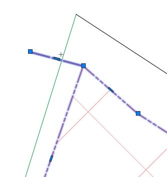
It is highly recommended that they contain no Curved segments. FarmBlocks are imported as segments of straight lines, and hence all curve information will not be considered. This does not cause an error. However, it may lead to unwanted confusion regarding intersecting routes. Consider the below example.
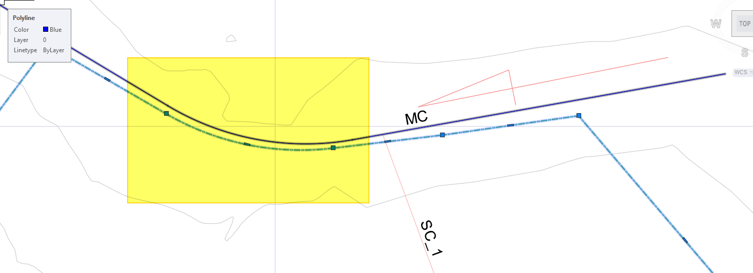
Here, the Farm-block corresponding to SC_1 has a curve tracing the curve of the main canal (as shown in the highlighted area.) Upon import to network, the curve information is not considered, and the Farm block will have the geometry shown below.
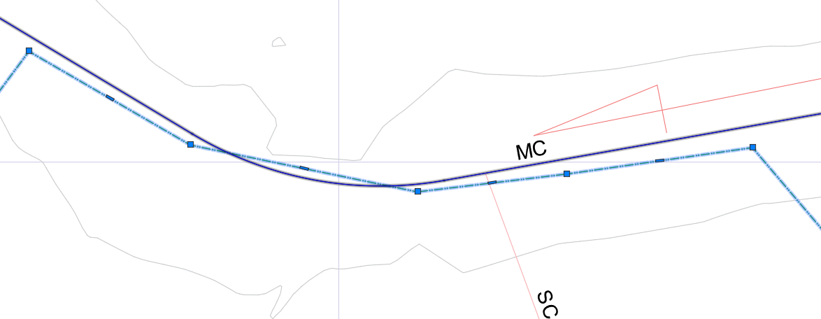
As a result of removing the curve, the farm block now happens to cross not only the intended SC_1 route, but also MC. This may result in linking of farm block to MC, instead of SC_1.
Important Notes about AutoGenerated Blocks
If the AutoEstimate tool is used to create Farm Blocks, then it is key to note the following assumptions used in the software:
-
Blocks are created for all canals who have EndOfCanal nodes associated with them. Typically these would be the lowest level or generation of canals in a network.
-
The farm block created for a supply canal will attempt to follow the path of the canal, constrained by the neighbouring canals.
-
For the last supply canal in a group, the farm block is created by using information from previous supply canal, and the alignment of the route itself. This is especially true, if the irrigation method is considered to be single side.
-
The farm block creation can take one of two possible methods for a given parent route. Assuming a TC canal feeding to QC canals, a single side irrigation is assumed if the initial distance to the first QC canal is less than 30m. Other wise, a double side irrigation is assumed. This assumption is used when creating farmblocks for all the QC canals.
Sizing Networks
Sizing networks is a quick process, that fully relies on the farm block data prepared using the above steps. It determines the amount of water discharge that must be transported in each segment of the each route of the canal network. To start the fully automatic process:
-
Make sure there are no selection(s) in the plan view, by right clicking on the layout view area and selecting
Clear Selection. -
Start the menu command from
Workflow > Network Rating/Capacity.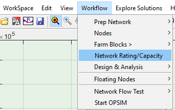
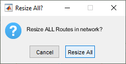
-
Choose
Resize AllThis will do the calculation for the entire network, and display the resulting information in the layout view area. If no information is shown, toggle the text comonent fromView > Route Text > Toggle Text On/Off.
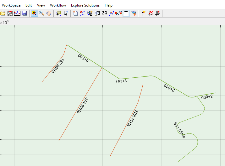
Note that text label for canal capacities follow the notation X+YYY, where X denotes capacity in cubic meters per second, and YYY denotes capcity in litres per second.
END.