CanalNetworkDocs
Layout plans and Network Resolution
Refer to the standard workflow for using CanalNETWORK software. One of the input data is a layout map in AutoCAD. This section discusses the task of importing such a layout map from an AutoCAD environment, and processing the connectivity data for the network of canals. Most of the task is handled automatically, while it needs some assistance from the user to resolve some issues that may linger.
AutoCAD canal layout maps
The AutoCAD layout maps must fulfil certain conventions to be used in the CanalNETWORK software environment. The following are essentially assumed to be true in the AutoCAD source drawing:
-
All routes are drawn using Polyline command. Any object drawn with the Line command can not be processed, and will be excluded. It causes error on subsequent tasks.
-
All canal routes are drawn from upstream to downstream directions.
-
All canal routes start and end with a stratight segment of at least 20m.
![[ ]](Images/Image%20001.png) Maintain straight segments at begining and end of canal alignments
Maintain straight segments at begining and end of canal alignments -
All canal routes are drawn to scale of 1:1, and referenced to world coordinate system (WCS) of AutoCAD.
Best practices for layout drawings include, but are not limited to:
-
Organization by layer: it is very helpful to collect canal routes of similar generation or level to one layer. Users have, while working on a number of projects, observed that this will greately enhance key batch tasks later. For instance, collect all TC (teritiary canals) to a separate layer, say TC Canals. Similarly, collect all quaternary level canals to a separate layer called, say, QC Canals. And so on.
-
Intersection of canals: The points where any two canals intersect will form a junction node. Nodes constitute the basic data block for network analysis. Therefore, all canals must be drawn with care - especially near the begining and the end. The following are key recommendations:
-
where two canals offtake from a single parent canal, make sure they intersect the parent canal at the same point.
-
Where two canals offtake from a single parent canal, make sure they do not intersect themselves any where other than the point where they intersect the parent canal. This may be the case where the starting segments of the branch canals are either parallel, or the cross the parent canal at slighly different locaitons. If necessary edit the first or second vertext of one of the canal routes to avoid parallel.
![[ ]](Images/Image%20002.png)
- Intersection of branch canals with a parent canal* * If possible avoid curves on a parent canal where it intersects with branch canals.
-
-
Except where brnaching is needed, avoid extending the end of canals anywhere close to other canals, and certainly not with in the extension distance (specified in Network Preferences). Failure to observe this will result in unintended junctions leading to significant time in correcting the connectivity of the network.
![[ ]](Images/Image%20003.png)
Desired network relation ship.
![[]](Images/Image%20004.png)
Unintended Junction at a canal end potentially confusing canal parent-child relation ships 3. All routes should end at sufficient distance from other canal routes. (Sufficiently farther than the extension length and node merge distance parameter values in
Network Preferences, which are often set at 2m and 5m respectively.)
Note: The amount of time spent to resolve a network analysis, depends little on the size of the irrigation area or the number of canals. Rather it greately depends on how strictly the above guideline is adhered to in preapring the layout map.
For this reason, it is highly recommended that the engineer responsible for preparing layout maps must be aware of these guiding rules and assumptions.
Network resolution: Definition
Network resolution is a term used to represent the task of analysing the connectivity between each canal route in the canal network system, and ensuring that each canal in the network has ONLY one parent canal.
Where this basic criteria is not met across the system of canals, the network is NOT resolved, and progress to the subsequent steps (for instance Network establishing in the standard workflow) is bound to abort with an error of some sort.
After a succesful network resolution task, the user can do the following:
-
Automatically generating ordered and sequentila naming for all routes in the network.
Some canals may need to be manually named depending on specific needs of the project. These canals can be assigned NAME EXCEPTIONS. A common example is a TC branching from another TC. This route will be automatically named a QC, but the user can assign in a TC level as an exception.
-
Plot these namings to AutoCAD environment with desired text specification (height, font,…)
-
Use the resolved network structure to group canal routes by generation and instance them in AutoCAD, for batch processing at a later stage.
Note: See below on exceptions and their naming convention.
Lets now see how layout maps prepared in AutoCAD are imported to CanalNETWORK environment and analyzed for connectivity.
Importing layout map to CanalNETWOK environment
The first step is to import the drawing to the CanalNETWORK environment. There are many ways to do this:
-
To import a individual routes - i.e., a single route at a time - Go to
Workspace > Pick Route (AutoCAD).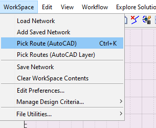
-
To import alignment routes drawn on a layer, go to Workflow > Pick Routes (AutoCAD Layer). This will invoke a dialog listing all the layers in the current drawing.
![[ ]](Images/Image%20007.png)
Pick the desired layer, and hit OK. This will import all alignment routes found on the specified layer to the plan view area.
Note: This method is recommended for drawings whose layers are well organized, especially for the different levels of canals expected in the project.
-
One can also import a collection of canal routes at once. To do this:
-
First, create an instance of all the canal routes on a host object with in the AutoCAD environment, using the AutoCAD addon tool.
-
Then go to
Workspace > Pick Rotue (AutoCAD)menu command, and when prompted pick the host object.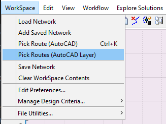
This will import all the canal routes instanced in the host object.
-
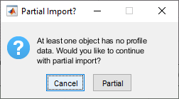
Note: A complete canal route data consists an alignment data (x, y) and a profile data. The below $Partial Import?$ prompt may apear when importing canal routes whose profile data is not yet extracted. This is perfectly acceptable, and proceed by hitting
Partialbutton. Partial meanse that only the alignment data will be available with out the profile data. Also, note that routes imported with partial are represented with broken lines in the plan veiw area of the interface.
![[ ]](Images/Image%20010.png)
Routes in plan view area showing canal routes with complete data set, and partial data set.
Every time, the routes are generated drawn in the plan view area of the interface.
Remember, alignmnet routes that are NOT drawing as polyline, and whose length is less than 20M will be filtered out, and hence can not be imported.
Removing Unwanted Routes
Unwanted polyline objects may be imported to the plan view area during the process of importing canals. Also, the user may want to remove a canal route and re-import it again. To remove such objects:
-
Select the objects to remove in the layout view (plan view) area. If needed, enable multi-select from
Edit > Multi Select (Routes)to allow selection of multiple routes at a time. -
Use
Edit > Remove Routemenu command.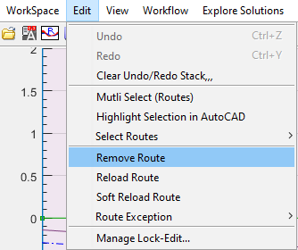
![[ ]](Images/Image%20011.png)
Delete dialog requesting confirmation for selected routes.
Once all the canal routes are imported, the next step is Node Identification.
Node Identification
The term Node is used to represent a location on a layout map that represents key locations along canal routes. There are three types of nodes.
-
Canal junciton nodes: are created where a branch canal meets a parent canal. These are represented as circles. These are represented as Circles.
-
End of Canal Nodes: are created where a canal route terminates with out connection to a branch canal. Such nodes are represented as squares. These are represented as squares.
-
Floating Nodes: are created by the user to represent any changes in physical or hydraulic, or other information along a canal route. This types of nodes are not relevant for the current topic of Network Resolution, but are discussed in detail in the section Longitudinal Design of Routes.
![[ ]](Images/Image%20012.png)
Figure showing appearance of Junction Nodes and End-of-Canal nodes in layout view area.
Note: The size of the nodes as they apear on the plan view can be customized in Node graphic.
CanalNETWORK can automatically analyze all imported canals to identify and insert nodes as needed. Node identification is invoked from Workflow > Nodes > ID Nodes menu command.
Note: It is recommended to change the view to layout view. The other parts of the interface are not of much use at this stage.
-
To identify nodes for selected routes, first select the desired routes and start the command.
![[ ]](Images/Image%20014.png)
Figure showing the confirm dialog before Node Identification process.
This will invoke the Confirm dialog requesting confirmation on the number of canal routes currently selected for the process. Click
Yesto continue. -
To Identify nodes for the entire network of canals, make sure there are no selected routes in layout view area (right click and hit
Clear Selection). Then start the command.![[ ]](Images/Image%20015.png)
Figure showiing confirm dialog before Node Identification process for entire network.
This will invoke the confirm dialog as above. Please note the number of rotues to be addressed in the dialog to differentiate between the two cases.
The process will automatically generate Nodes for the desired routes and display them. The generated nodes now represent parent and branch canals at every junction in the network. Often, the connectivity between canal routes will not be perfect to desired conditions. This is ALWAYS because the conventions and assumptions listed early in this section are not observed fully during layout preparation in AutoCAD drawings.
Most of these connectivity issues can be identified automatically, as discussed below.
Identifying Connectivity Issues and Resolving them
The user may expect two types of isses with the connectivity established from above step.
Missing Junction Nodes
Rarely, the algorithm seems to miss nodes where there should be one. Apparently intersecting canals may not have nodes after the NodeID process described above. Such a case is shown below.
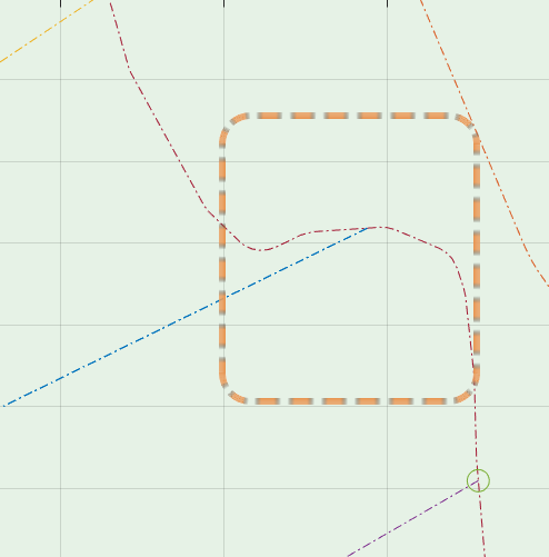
In this case the user can introduce nodes manually.
-
Relax the Route Extension Length parameter in
Work Space > Edit Preferencesto a reasonable figure depending on the distance bewtween the begining of the branch canal and the apparent intersection point with the parent canal. Usually a value of 2 meters gives good results. (Note: Max allowes is 5m)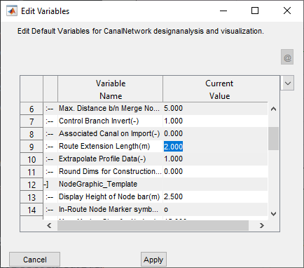
-
Select the parent and branch canals. Make sure to enable multi-select from
Edit MultiSelect (Routes), to be able to make two route selections. -
Run the Node ID process from
Workflow > Nodes > ID Nodes. This will automatically prompt you for possible actions.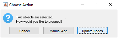
Choose
Manual Add. -
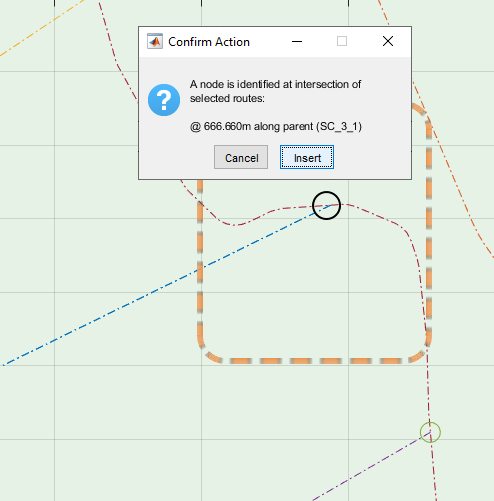
If succesfully found, a dialog will display the location for the newly found node as shown below. Hit insert, and node will be inserted.
Unresolved EoC nodes
The first common issue is locations where End-of-Canal nodes are inserted, instead of a Junction node. This condition misses to understand that there is a branch canal leaving from the end of the parent canal, impairing further work during canal design. It must be resolved.
![[ ]](Images/Image%20016.png)
Wrongly created EOC Node instead of a Junction node.
There are two approaches to resolve such issues. Manual and Automatic methods. The manual method allows to resolve individual issues.
-
First right-click on the branch canal to select it.
-
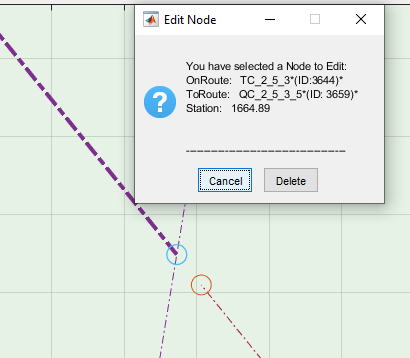
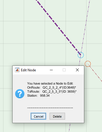
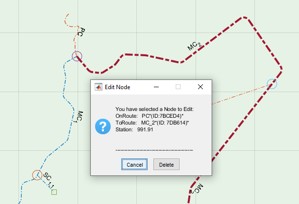
Then left-click on the EOC node to be corrected. This will invoke the Edit Node dialog, detailing the current connectivity status at the specific node.
![[ ]](Images/Image%20017.png)
Edit Node Dialog for the EoC node
-
Click on the
To Current Nodebutton to link the picked route to the node. This will correct the issue, also changing the square node marker to a circle node marker correctly representing a canal junction.![[ ]](Images/Image%20018.png)
Resolved Junction Node at End of Canal.
Oftern however, there are too many EoC nodes that must be corrected or resolved in a network. This is especially true after the first attempt to ID nodes for a complete network of routes. The automatic tool is helpful in this situation. To use it, go to Workflow > Nodes > Convert EoC Nodes menu command.
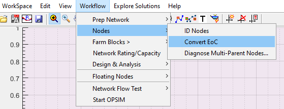
![[ ]](Images/Image%20020.png)
Confirm Operation dialog.
This will identify all wrongly positioned EoC Nodes in the entire network database, and correct the issue one-by-one, also informing the user of the progress.
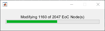
![[ ]](Images/Image%20022.png)
Progress bar and message at end of operation informing the user of how many EoC nodes are succesfully converted.
Mulitple Parent Nodes
The key purpose of node resolution is to ensure that each branch canal has only one parent canal. However, some canal arrangements may mislead the software and assign two routes as parents for a single brnach canal. Again, this ALWAYS happens when the assumptions and conventions listed early in this section are not fully observed during layout preparation in the AutoCAD environment.
CanalNETWORK can automatically locate these nodes in the network. The user must manually resolve the issue.
To identify nodes where multiple parent condition may be an issue, go to Workflow > Nodes > Diagnose Multiple-Parent Nodes. If found, the command will list such locations in a table.
![[ ]](Images/Image%20023.png)
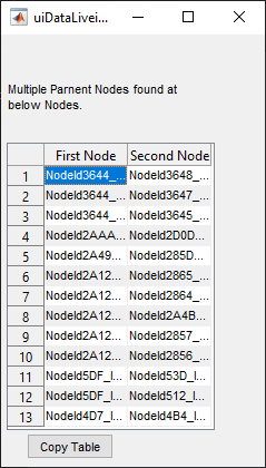
Menu command and resulting table for Multiple Parent Node issue identification. The table shows both First and Second Nodes refering to the same branch canal (not shown in the table)
Once this is ready, the user can navigate to each location and resolve the issue. To go to a particular node listed in the table, select it in the table, then use View > Go To Route... menu command, or simply click on the interface and use Ctrl + G keyboard shortcut:
![[ ]](Images/Image%20025.png)
Go to Route menu command
The layout view will pan and zoon in to the desired node location.
In the table list of nodes shown above, both nodes refer to the one branch canal. This can be noted by left-clicking on each node, one at a time. It can be seen that the Edit Node dialog lists the same branch canal to each node.
Obviously, the lower-right node is the issue. This is because, it is the end of a canal and no branch is expected or implied in the drawing. What caused this issue is the fact that the canal in question ends very close to the begining of the other canal. The AutoCAD drawing measurement confirms this.
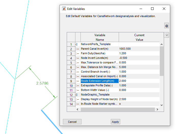
AutoCAD measured distance between end of a canal and begining of another canal. Based on the preference (shown to the right) search radius for a neighbouring canal is 2x2meters (4meters) locating the wrong canal as a parent canal.
To resolve the issue:
-
Left-Click on the route for which multiple parents are assigned. It will be selected.
-
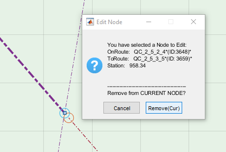
Left-Click on the mistaken Node (lower right inthis case). This will invoke the Edit Node dialog.
-
Click on the
Remove Curbutton. This action will do two things: detach the branch canal from the node, and convert the node to EoC node.
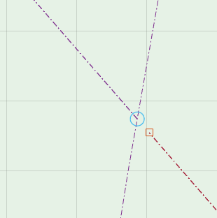
The issue is resolved. Repeat the above steps for all other such nodes.
Before continuing to the next step, Re run the test Workflow > Nodes > Diagnose Multiple-Parent Nodes... to verify all issues are succesfully resolved, or new issues are not created in the process.
Network Preferences
Much of the work carried out above, and some that will follow, are dictated by settings in the network preferences variable set. As such, it is important to understand how they are used. The variable set is accessible from Workspace > Edit Preferences
The meaning and use of each variable setting is described below.
| S.No. | Variable Name | Description | Default Value |
| Network_Prefs_Template | |||
| 1 | Parent Canal Invert(m) | Desired invert level of the primary level canal | -0.8 |
| 2 | Farm Duty(l/sec/ha) | Designed duty for the farm area. Note: This is overriden by settings in the design criteria. In latest releases (Version 1.5) this variable can be set to 0 to force node invert location to always meet downgrade conditions wrt to upstream nodes. |
1.2 |
| 3 | Node Invert Levels(m) | Default invert levels for positioning nodes (or controls) defined relative to OGL at location. | -0.5 |
| 4 | Max.Tolerance to compare FSL(m) | Maximum tolerance value to be used in comparing FSL values, especially used in flow test tasks. Please refer to relevant material on flow test tool. | 0.005 |
| 5 | Max. Distance b/n Merge Nodes(m) | Any nodes found with in this distance range are merged together, and will be treated as one node. | 5 |
| 6 | Control Branch Invert(-) | Position of invert levels for branch canals at node location. There are two options: 0: Lock with Node – the branch invert is set to parent invert, or hydraulically determined level, which ever is minimum. 1: Free from Node: branch invert is fixed based on hydraulic calculations regardless of parent invert level. |
1 |
| 7 | Associated Canal on Import(-) | Import associated canal flow section on each route during import. Applicable only in older versions. | 0 |
| 8 | Route Extension Length(m) | Extension length for beginning of routes, while attempting to establish intersection with other canals. In latest releases (Ver 1.5 and latter) with the modified Node ID algorithm this is used to create the buffer zone arround canal routes to locate intersecting routes. |
0.1 |
| 9 | Extrapolate Profile Data(-) | Allow or deny extrapolation of transverse profile data beyond the limits of the offset range, if needed. | 1 |
| 10 | Round Dims for Construction (-) | Rounding value for bottom width of canal flow sections, and drop provission. Value >=0.05 rounds B values to Value specified, and drop heights applied will be limited to allowable increments specified in CBL_designSettings assembly parameter. |
0 |
| NodeGraphic_Template | |||
| 1 | Display Height of Node bar(m) | Height of nodes or control markers in the profile view area. | 2.5 |
| 2 | In-Route Node Marker symbol(-) | Marker to be used for representing junction nodes. | o |
| 3 | Max. Marker Size for Nodes(Pnts) | Largest size of markers in layout view area | 15 |
| 4 | Min. Marker Size for Nodes(Pnts) | Smallest size of markers | 10 |
| 5 | End-of-Canal Marker symbol(-) | Markers to be used for representing End-of-Canal Markers | s |
| 6 | Marker Size for EOC(pts) | Size of EoC markers | 10 |
| 7 | Available Head Margin(%) | Percent of flow head to be considered during flow test tasks, when determining available heads. (Please refer to flow test tool details) | 1 |
| 8 | Text Font Height (-) | Font height to be used in display of text information in graphic display areas of the main interface. | 10 |
| 9 | Color template(-) | Color template to be used in creation of profile, plan and section details. The colors are also used in generating AutoCAD drawings. | Default |
| control_BoQSettings | |||
| 1 | B/H ratio (wall) | Ration of width to height of vertical structures (eg., drop falls), to be used in calculating volume of concrete/massonry. | 0.65 |
| 2 | Excavation cut slope | Cut slopes to be assumed for controls (turnouts, divisionboxes) and drops, when determining excavation volumes. | 0.25 |
| 3 | Working space(m) | Amounf of working space to consider in volume calculations for above, | 0.3 |
| 4 | Compacted fill Ht(m) | Height of compacted fill to be considered in determining both cut and fill volumes for above. | 0.1 |
| 5 | BoQ List of Items(-) | The level of detail desired for BoQ report gerneration: could be set to either detailed (default) or summarized. | Detailed |
Note: Invert levels -0.5 denotes, to use the OGL level at the begining of the canal less 0.5m. It is defined relative to the OGL at the point of interest.
Bottom width roundup value also forces minimum allowable width to 0.30m.
Generating Canal Naming for the Resolved Network
Generating a naming - cross-referenced - labels for each canal route in the network is a true test of fully resolved network, that guarantees smooth workflow in subsequent network analysis and design tasks.
To create a desired naming for the network of canals just resolved, first a naming style is needed.
Defining Canal Naming Style
There are multiple styles available to generate a canal naming, depending on the project type, scale and user preference. To create a naming style go to Workspace > Manage Design Criteria > New Namiing...
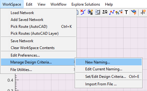
This will start the Edit Variables Dialog, set each variable to desired values as follows:
-
Canal Network Naming: This prescribes the exact sequence of naming to be followed begining from the primary level (1st generation) canal all the way to the last level of of canals.
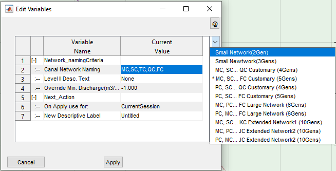
Available options for Canal Naming
-
Level II Desc. Text: Defines the text to be used 2nd level (2nd generation) canal rotues in the network.
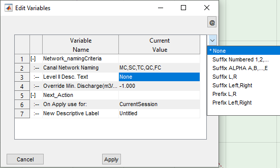
Available Options for Descriptive texts
-
Over-ride Min. Discharge: The setting for this variable is overwritten in the design criteria. Hence users may leave this to the default value of -1 (representing None)
-
Next Action: On Apply Use For: leace as is
-
New Descriptive Label: Optional string to spefify the naming style defined, to help easily idenfity for latter use.
Note: All inputs must be selected from the avaiable options, and no custom inputs are accepted.
As a best practice, it is always recommended to use a naming with sufficient levels (at least a few levels longer than expected ) to label all generations in the network. Otherwise, erros will arise further lengthenning the tiime taken to resolve the network.
Upon completion, hit the Apply button. This will invoke the Get Design Criteria? dialog. It is essential to confirm to this dialog with the Yes button.
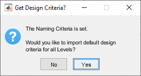
Get Design Criteria dialog
This will import the default design criteria set for the network data, which can latter be altered to meet specific design conditions.
Creating the naming list is completed here. The next step is to attempt to generate canal naming to each route, and resolve any remaining issues in the network.
Create Naming
To create names for each route in the canal network, based on the naming style just defined (above):
-
Select the primary level canal for the project by left-clicking on it in the layout view area.
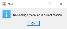
If a naming style is not defined yer, the below dialog will terminate the process. Define a naming style and try again.
-
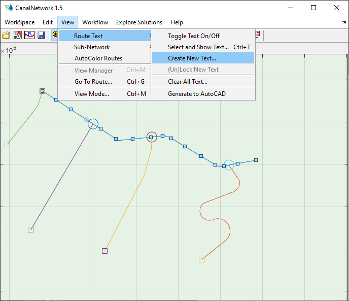
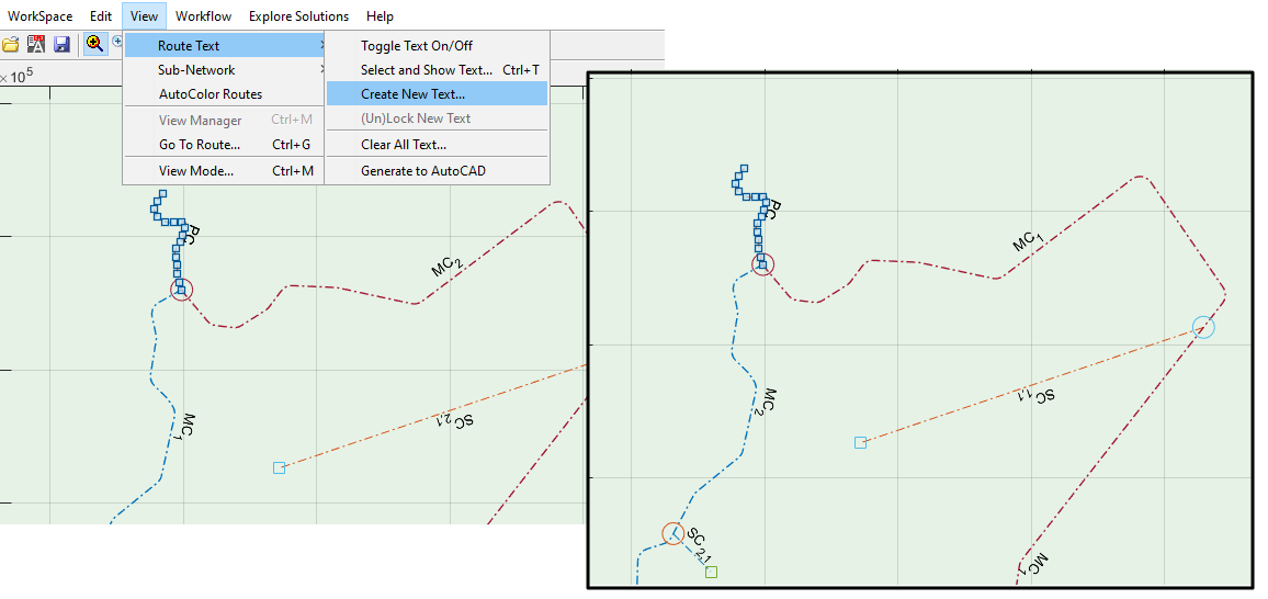
Go to View > Route Text > Create New Text… A process dialog such as shown below may apear. Choose
AutoStack and Repeatuntil all issues are handled, or the number of issued does not reduce any more.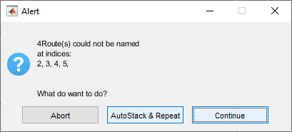
-
Choose Tag on the dialog, and hit
OK.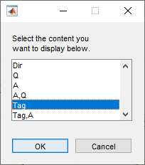
A naming style is generated per specifications, and applied to each route. A table also lists the naming applied to each route ID.
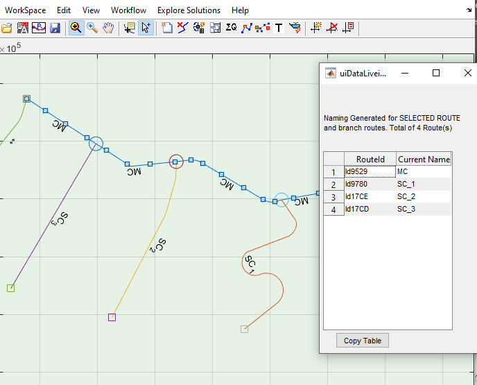
A network data is accepted as fully resolved if all routes are succesfully named with appropriate level indices.
Beware of double astrisk (** or place holder) strings. These indicate routes whose connections have not been resolved fully in earlier node identification and resolution process. In the screenshot above, for instance, the last route has an issue. It can be seen that the connecting node to the parent canal envisages and EoC node, and not a branch junction node. This must be resolved to get the correct naming. Pan and zoom in the entire network area to see if there are any ** labels and resolve any issues causing them.
FInd Text dialog invoked using Ctrl + F keyboard combination.
Use Ctrl + F keyboard combination to search for such texts in large networks. If found, they will be highlighted for easily locating them.
Note: Some times, you may need to change the name of a parent canal. For instance for canal exceptions. In such cases, the branch canal naming must also change accordingly. Or you may just want to re-create the text. You can easily achieve this by running
Edit > Route Text > Create New Textcommand for the desired route.
Exceptions for Canal Routes
In some cases, the automatic assigning of a generation to a canal route may not serve the needs of the project. For instance, a canal may need to be designed as a TC route despite its parent canal is an MC or TC canal. To allow such unusual design requirements, the exceptions method is available. This allows to manually assign a generation or level to a route.
Setting Exceptions
To manually override the naming for a canal route:
-
Click on the canal route whose route name is to be manually changed.
-
Go to
Edit > Route Exception > Exception for Current Route.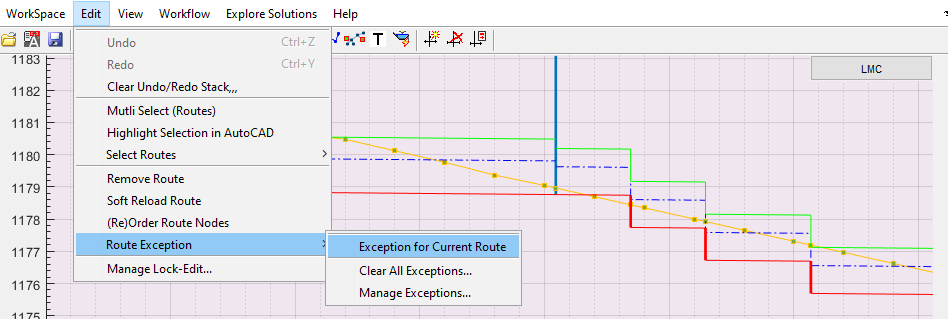
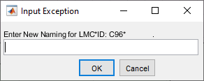
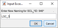
This will invoke the dialog box to manuall insert the desired canal naming.
If a previous exception is found, a dialog similar to below will apear showing more information, and also requesting for confimation of action.
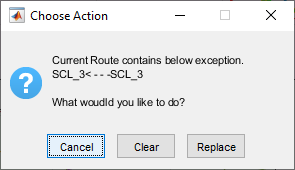
If
Replaceis confirmed, the above dialog Input Exception is displayed. -
Input the desired exception naming in the dialog.
Note the following requirements:
-
The first letter has always to be an alphabet
-
No brackets, hyphens, or special characters are allowe, except the under-score symbol.
-
The name must be formatted as [prefx]GEN[suffix]_numbering1_numbering2 …
-
GEN must be an exact match to one of the generations defined in the naming style for the project.
-
Prefix OR suffix are optional. If provided, they must match the prefix or suffix settings defined in the naming style for the project.
-
-
Click on
OKto confirm manual override. The naming is applied to the route selected. -
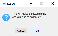
Note that manual overrides means, a different design criteria is required fot the route in question. Hence, a dialog requesting to confirm resizing operation is displayed. Confirm to proceed.
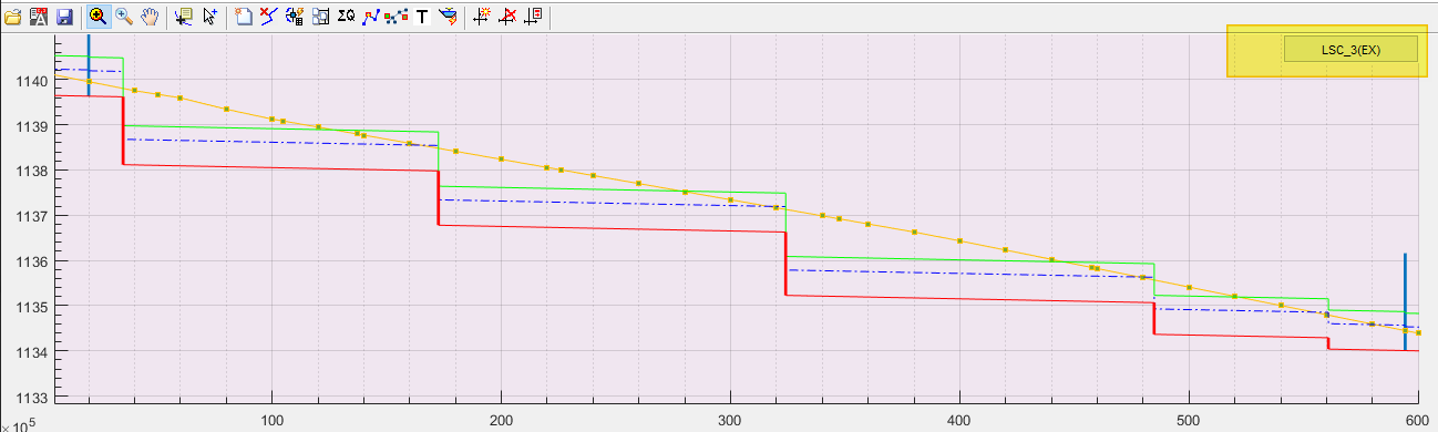
This completes the exception definition process. Note that canal routes named with exceptions have their names (in the profile view) displayed with an (EX) suffix, as shown in below example.
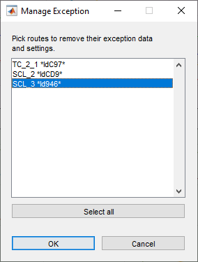
Managing Exceptions
You can manage the exceptions set for the entire project in one place.
-
Start the command
Edit > Route Exception > Manage Exceptions....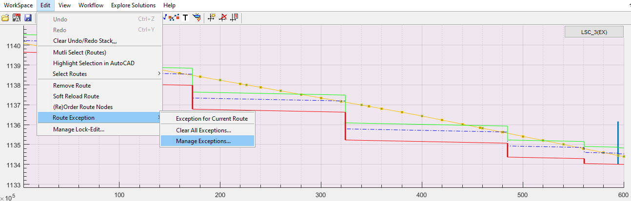
This will list of all exceptions set for the entire project data.
-
Select the route whose exception data you want to remove, and click
Ok. Note that the displayed route names are as per current exception naming set. The below confirmation dialog appears.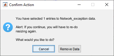
Note: This dialog also warns that resizing must be manually handled. So apply resizing on the route, before proceeding to design immediately after this change.
-
Click on
Remove Datato confirm your action. This will (a) remove all exception data for the selected route, and (b) re-instate the original naming for the route, which is created during the initial canal naming task.Click on the route again, to see its rolled back naming on the profile view.
Note: The original naming for routes (generated automatically) may not be available, especially after repeated renaming. If you want to re-instate original naming, clear all exceptions for the project (or the deisred route), create route naming text as new and proceed.
If you want to clear all exceptions set for the entire project, choose View > Route Exception > Clear All Exceptions... menu command, and confirm to the dialog box.
Notes on Eceptions
When working with route name exceptions, it is important to note the following behaviours.
-
No limits to the number of exceptions that can be set in a given project.
-
Exceptions are persistent, retain the value set even when new name creation is requested from
View > Route Text > Create New Textmenu command. -
The naming style should be strictly consistent with the currently defined naming style. If naming style, or its parameters, are changed (which is not recommened), errors in data processing are bound to occur and difficult to resolve easily.
Rendering Names to AutoCAD
The canal namimng generated as described above can be exported to the AutoCAD environment to label each source alignment object of the canal network accordingly. To export naming:
-
Make sure the desired text is displayed on the layout view area. Toggle the text view button on if not already. Use
View > Route Text > Select and Shot Text...menu command if not already.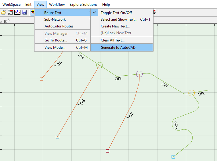
Sample Layout map with Canal naming displayed.
-
Choose
View > Route Text > Generate to AutoCADmenu command. This will invoke the Sample Text dialog.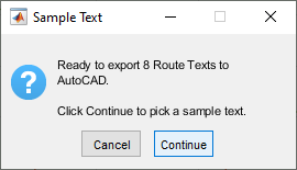
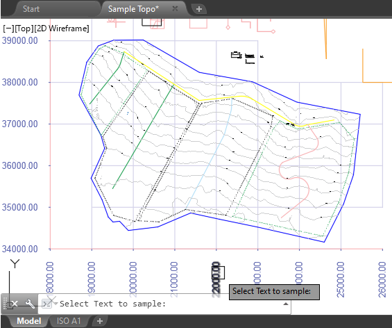
-
Choose
Continuebutton. AutoCAD environment is now in select mode waiting for user input. Pick a sample text.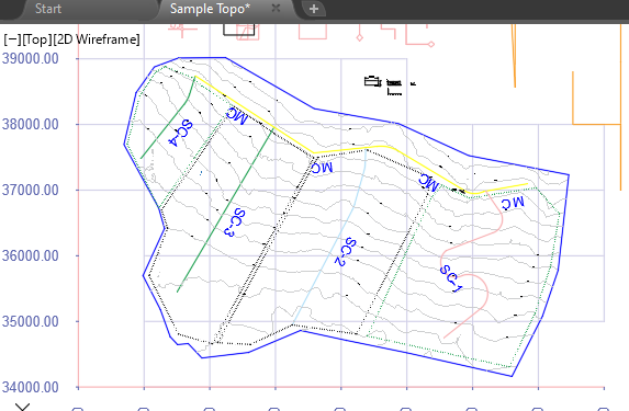
All texts are generated to AutoCAD environemnt using the text height of the sample text selected above. Other similar information, for instance Area and Discharge capacity, can also be generated using this method.
Tips on Network Resolution
Swapping Canal Order for Naming
The order in which canal branches are read in to a node is on first-found first-registered basis.
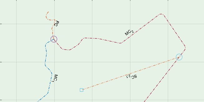
In the above figure, the Right side (Facing downstream) canal is registered, and the left side registered last. Hence, the naming MC_1 and MC_2 respectivly. To change the order of such branches:
- Select the MC_1 route, and click on the branch node. On the Edit Node dialog, use
Remove (Merged)button to remove the branch.
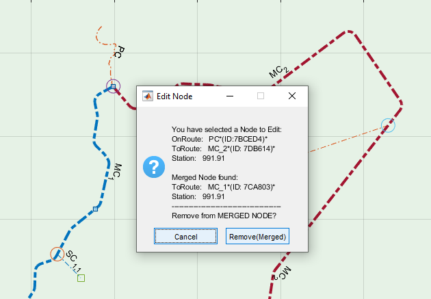
This will leave only the other route (MC_2) connected to the node.
- Then, select the MC_1 route, and click on the node again. This time, the Edit Node dialog offers a different option. Click on the
New Merged Nodebutton.
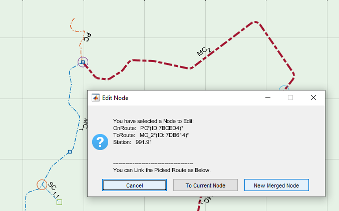
This will ensure that right side canal (facing downstream) is registered next to the left side canal. To see the changes in action, select the PC route and run View > Route Text > Create New Text... menu command. You can see that the names are swapped as desired.
Important Note:
Recreating Nodes on a route, or on an entire network, causes loss of floating node information, as well as related information created including data on design of structures.
END.